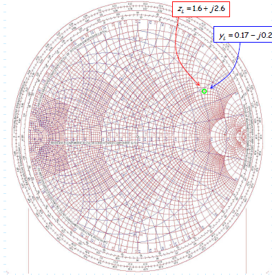

#Admittance smith chart windows
Z-Match for Windows / Number ONE System Limited 1994.Norm Dye and Helge Grandberg : Radio Frequency Transistors / Butterwoth Heinemann 1993.Henne Fachhochschule Augsburg : Die Smith Chart 1963. Transforming of impedance’s to Admittance’s and vice versa.7 Wave length circle l/lambda to generator.5 Constant resistance R/Z circles with negative reactance scale.4 Constant resistance R/Z circles with positive reactance scale.3 Reflection r circles, radius scale is outside.In a real paper smith chart all circles are combined in one chart Fig.4. Summary of all impedance smith chart circles. The main purpose of the Smith Chart is to match RF and microwave units, filter and line inputs and outputs, to get a small reflection r = p =15 to 30 dB.įig.3 Wavelength circles in the Smith chartįig.4 Summary of circles in the Smith chart. These are just scales, the reflection itself is somewhere within the outside maximum reflectionĬircle.
#Admittance smith chart generator
3 shows these circles, either toward the generator (blue) or to the termination resistor ( red). We get : The reflection circle for wave lines is therefore scaled in normalized values of the line length Using wave lines, the reflection is an other circle pointer: The reflection here is dependent on the propagation. Even the solutions of large equations, when simplified with a computer program to u + jv. It is obvious that in place of reflection, all the other complex values Here, the impedance’s in the Smith Chart are normalized to standard The reactance circles outside from reflection circle p = 1 are cut off.

Within the maximum reflection circle r = 1, leads to the basic Smith chart of Fig2.

One for the resistance’s and an other for the reactances: The graphical representation of these circles Normalized resistance and reactance circles.īecause reflection always is the result of a complex input device or a complex load or both, we can write the reflection in the following equation:Īfter some algebraic work, the result for the reflection is a quadratic equation with two circles. So normally, in case of p >20dB we donut care about the attenuation ripple.įig.1 Reflection circles in the smith chart The reflection of electronic circuits is too a measure for the attenuation ripple: A normal reflection of 20 dB then will An other parameter depending from reflection is the ratio of the voltages: In Smith, paper charts are outside the circle, a reflection scale, either with r / dB or It is only the outer loop for the total reflection visible.The other reflection circles, are invisible,Īnd the designer must know that there are such circles. Reflection circles with Smith chart background. The total reflection circle is the base circle of the Smith chart. The pointer p = r is 0 for a totally matched system, or 1 at total reflection. This leads to a pointer with a 360 ° circle. The reflection is dependent on the impedance of the wave line, the length of the wave line and the complex load impedance. Now there are two waves, a forward wave into the load and a backward wave from the load An RF generator isĬonnected by a wave line on a complex load R =W. This RF development diagram is the sum of four basic circle diagrams :ġ Rotation of the reflection circle pointerĤ Normalized reflectance versus wave length lineĮlectronic reflection is the result of not matching connections of electronic RF devices, cables Here is a careful explanation of the Smith Chart :
#Admittance smith chart series
Matching-example #10, parallel resonator and series resonator as matching circuit.Matching-example #9, using parallel stubs.Matching -example #8, matching with different Z and Capacitor.Matching-example #7, several wave lines having different Z.Matching-example #6, matching from input and from the output.Matching-example #5, using only one Wave line.Matching example #4, transmitter output power transistor.Matching example #3, component and tramsformer.Electronic matching, using the smith chart.The wave guide resonator in the smith chart.The series resonator in the smith chart.The paralell resonator in the smith chart.Working with the impedance / admittance Smith Chart in a graphic software.Summary of all impedance smith chart circles.Normalized resistance and reactance circles.T he Smith Chart, a practical electronics course.


 0 kommentar(er)
